 |
MODELLING A GLASS
By Olivier Saraja |
 |
|
MODELLING A GLASS
By Olivier Saraja |
|
There's a major topic that haven't been discussed yet, while it has a clear influence ont the rendering samples showed earlier in the tutorial : lighting !
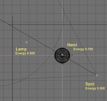
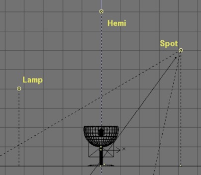
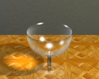
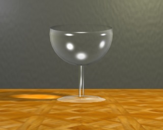
For this scene, I added a lamp (Energy 0.500) to the left of the glass, a Hemi (Energy 0.700) above it, and a spot (Energy 0.500, 'Only shadow' turned on), slightly on the foreground and to the right of the glass, as shown on the two following pictures.
 .
.
As a last step to enhance the realism of our scene, we will simulate the appearance of caustics, e.g. the flocks of light that show in the shade of a glass object, light warped and concentrated by the roundness and thickness of the glass. In order to simulate this phenomenon, move the glass on the second layer of the scene (M-KEY and then select the second little squarre from the left). Now select the spot and make a copy of it with SHIFT-D and call the Lamp Buttons (F4-KEY). Deselect the 'Only Shadow' button but select 'Layer' instead, because you don't want the glass to be lighted by the light. Set the lamp parameters as shown hereafter, and especially the Energy 3.500 and SpotBl 1.000 parameters.
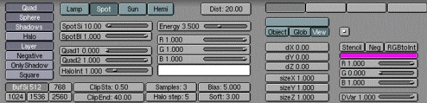
You will certainly have to make many intermediate renderings in order to set the correct location (regarding Loc and Rot) and the SpotSi that you need for your scene. The spot should point a the very heart of the glass' shade ! Within a few guess-and-try, you sould be able to find the most visual striking location, which should make its way through the geometrical center of the glass ball.
 .
.
You now have a very last render to do in order to enjoy the result, which should be satisfying enough until NaN develops for Blender some control over indices of refraction ! We are yet a long step from absolute realism, but this trick should be sufficient to lure the non-expert into a good illusion of reality.
 .
.
L a s t w o r d s f r o m t h e a u t h o r :
* about refraction: a common method used to fake refraction (the bending of objects seen through the curves surfaces of a glass) is to apply to the object an EnvMap texture map, and to set in the Material Buttons (F5-KEY) negative values of SizeX, SizeY and above all SizeZ (a 'minus' sign inverts the picture ; thus SizeY -1 inverts the mapped texture upside-down). For instance, we commonly see SizeZ -5.000 as a starting work value. The mapping should be done with the Nor or Ref toggled on instead of the default traditional Orco button. However, the refractions resulting from this method are barely realist or satisfying, from my point of view, and ask for tremendous tweaking to finally get parameters like SizeX -0.1, SizeY -0.1 and SizeZ -2.5. The more strange is that the experienced user of this method render similar pictures on a raytracers in order to examine the refraction map to achieve, and then tweak the SizeZ and other parameters until the achieve a similar result with the scanline mode of Blender. Having not a raytracer nor the skill to use one, I never got satisfying results while faking refractions this way. If you manage to do it, remember me ! ;o)
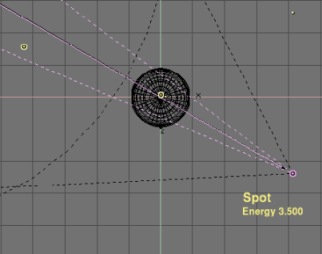
* about caustics : according to the shape of your glass object, you could have to use many spots in order to light the shade of your object a likely luminous area. Don't forget that you can get a square spot section by toggling on the 'Square' button ! In the folling picture, I achieved caustics with the proper stacking of many square spots.
|
|