|
by Xavier Michelon |
 |
||
| A r t i c l e s |
|
|
|
|
by Xavier Michelon |
|
||
| A r t i c l e s |
|
|
|
|
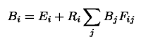
L'équation de radiosité Until now, we've talked about energy exchanges between patches. In the Global Illumination model, we will in fact use the radiosity, i.e. a light energy emitted per surface unit and per time unit. The symbol B is used for radiosity. All the energy exchange are ruled by an equation : the radiosity equation. It sums up all we have already seen :
The radiosity emitted by a patch i, noted Bi, equal the auto-emitted energy Ei (only for light source), plus the sum of all the radiosities received from the other patches in the scene. The Ri factor reflects the way a patch absorbs energy (it depends on the material associated with the patch). The Fij factor, called Form Factor, depends on the geometry, and is quite hard to calculate. Fij takes into account the distance between the patches, their orientations, and the presence of possible occluding patches (remember the figure in the previous section). The radiosity equation is the result of the simplification of a more generic equation (much more heavy too !). The generic equation contains double integrals and other funny mathematical stuff. The hypothesis made to obtain the radiosity equation would make a mathematician scream, but the important thing is too obtain a visually correct result. However, the consequences of those hypothesis are important :
|